|
Testschaltung
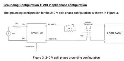 this configuration, the 240 V RMS AC output of the inverter is between terminals designated
AC (Hot 1) and AC (Hot 2). These terminals connect to each other through an isolation
transformer whose other coil is connected to the AC load bank that will apply the load profile as
discussed in the load profile section. The isolation transformer is center tapped on the inverter
side and connected to ground. This has the effect of fixing both of the AC (Hot 1) and AC (Hot 2)
lines to be 120 V RMS to ground, 180 degrees out of phase, similar to what would be found in a
North American household.
The purpose of the 100 Ω resistor and switch on the output of the AC (Hot 1) is to limit the inrush
currents into the transformer upon start up. The switch will be left open for a period of 10
seconds upon start up, and then will be closed.
Eingangsdaten und Ripple
this configuration, the 240 V RMS AC output of the inverter is between terminals designated
AC (Hot 1) and AC (Hot 2). These terminals connect to each other through an isolation
transformer whose other coil is connected to the AC load bank that will apply the load profile as
discussed in the load profile section. The isolation transformer is center tapped on the inverter
side and connected to ground. This has the effect of fixing both of the AC (Hot 1) and AC (Hot 2)
lines to be 120 V RMS to ground, 180 degrees out of phase, similar to what would be found in a
North American household.
The purpose of the 100 Ω resistor and switch on the output of the AC (Hot 1) is to limit the inrush
currents into the transformer upon start up. The switch will be left open for a period of 10
seconds upon start up, and then will be closed.
Eingangsdaten und Ripple
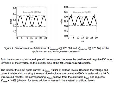 The limit for the input ripple current is IRipple less than 20% at all load levels. Because the voltage and
current relationship is set by the (near) ideal voltage source set at 450 V in series with a 10 Ω
wire wound resistor, the corresponding VRipple
follows from the allowable IRipple and requires
VRipple less than 3.0% (allowing for some additional losses in the system) at all load levels.
The limit for the input ripple current is IRipple less than 20% at all load levels. Because the voltage and
current relationship is set by the (near) ideal voltage source set at 450 V in series with a 10 Ω
wire wound resistor, the corresponding VRipple
follows from the allowable IRipple and requires
VRipple less than 3.0% (allowing for some additional losses in the system) at all load levels.
Vorgabedaten Specifikation
used to determine the grand prize winner.
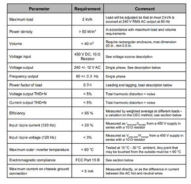 Parameter Requirement Comment
Maximum load 2 kVA
Load will be adjusted so that at most 2 kVA is
sourced at 240 V RMS AC output at 60 Hz
Power density more than 50 W/in
3 In accordance with maximum load and volume
requirements
Volume less than
Parameter Requirement Comment
Maximum load 2 kVA
Load will be adjusted so that at most 2 kVA is
sourced at 240 V RMS AC output at 60 Hz
Power density more than 50 W/in
3 In accordance with maximum load and volume
requirements
Volume less than
40 in
3 Require rectangular enclosure, max dimension
20 in., min 0.5 in.
Voltage input
450 V DC, 10 Ω
Resistor
See voltage source description
Voltage output 240 +/ 12 V AC Single phase. See description below
Frequency output 60 +/ 0.3 Hz Single phase
Power factor of load 0.71 Leading and lagging, load description below
Voltage output THD+N less than 5% Total harmonic distortion + noise
Current output THD+N less than 5% Total harmonic distortion + noise
Efficiency more than 95 %
Measured by weighted average at different loads
a variation on the CEC method, see section below
Input ripple current (120 Hz) less than 20 %
Measured as Ipeakpeak
/Iaverage
from a 450 V supply in
series with a 10 Ω resistor
Input ripple voltage (120 Hz) less than 3%
Measured as Vpeakpeak
/Vaverage
from a 450 V supply in
series with a 10 Ω resistor
Maximum outer inverter temperature less than 60 °C
Tested at 15 °C 30 °C ambient. Any point that
may be touched from the outside must be less than 60 °C
Electromagnetic compliance FCC Part 15 B See section below
Maximum current on chassis ground
connection
less than 5 mA
Measured directly, or as the difference in current
between the AC hot and neutral wires
Quelle: this document.
|
|
|
|
.
|